📻 Opus Build: The enlosure
Design
I’ve drawn dozens of design ons sketch paper: one with speakers next to the screen, some above or below it or even at the back or bottom of the object. At first I was aiming for sharp corners, similar to Amazon’s Echo Show, but all designs ended up looking too alien, ugly or large to have on a dressor in the living room. At some point in time, I switched to a more curved design, with aesthetics more reminiscend to the en vogue mid-century design of the 50’s.
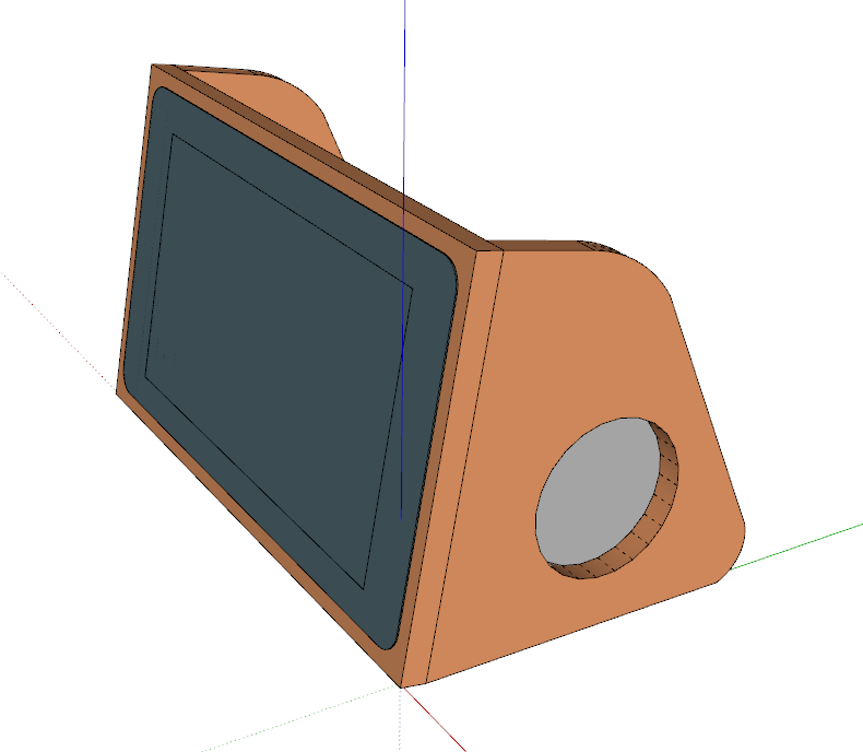
Design - front
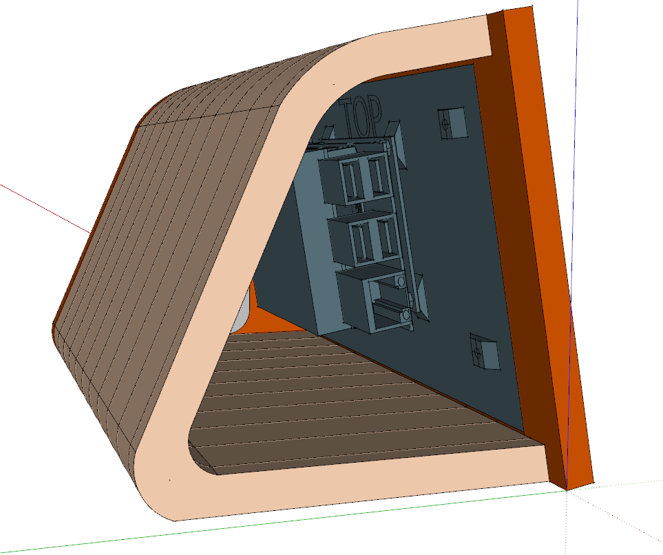
Design - back
This design was had a couple of benefits: it was small, had enough space to fit all the necessary internal electronics and has a visually pleasing design. Some additional character was added using two different color tones: darker front and side panels combined with a lighter body.
Transforming Idea into Reality
Now it was time to actually turn this idea into a reality. This meant some additional small revisions to the design in order to get the dimensions just right and the device structurally sound. It also meant it was time to think about how I was going to fabricate the device. For example: I’ve made sure the backside’s width is a multiple of 18mm, in order to use a common size of MDF board thickness in its construction.
The main body of the enclosure consists of 11 equal parts. We’ve been calling these pieces the vertebrae, due to their similar shape. These vertebrae are to be glued together to form the backside of the enclosure.
The fact that we’ll be veneering everything brings an added difficulty to the project: veneering around curved surfaces is tricky. To have good cohesion between the veneer and the backside, we require an equal pressure over the whole surface area. For this we’ve designed an inverse of the vertebrae which can form a pressure mould.
Instructing the Robots
The parts of our sketchup design are exploded into individual objects and exported as SVG. We’ve imported them in Inventable’s Easel web application. This simple GUI allows us to physically place the cut lines on the work area. Sincd the router bit being used has a diameter, we don’t want to cut on the lines, but besides them. After all, the lines indicate the outer edge of our object pieces, not the cutline itself. For a 1/8 inch bit, the cut lines are shifted 1/16th inch outwards.
The final design in Easel can be found here: http://easel.inventables.com/projects/f2RSPNxVxRgMM206p77NzA
The Carve
I asked around at various locations on price estimates for doing the carving and it quickly costs more than €150 euro, excluding materials. Luckily, my buddy has a Inventable’s X-Carve CNC router and offered to do the cutting for me. Using a 1/8 inch bit, the vertebrae are carved out of a single 80x60cm sheet of 18mm thick MDF. Another similar sheet is used to cut out the vertebrae for the mould.
In the video below you’ll see the X-Carve working away on one of the mould vertebrae. As the MDF is 18mm thick, it uses multiple passes of 1.3mm depth to cut all the way through. The two boards take about 4 hours to be cut.
Small tabs at the bottom are left uncut to ensure the vertebrae won’t jiggle around while being cut. Once finished the board can be flipped and the tabs cut with an x-acto knife. You can see them well in the photos below.
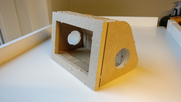
Rough cut - front
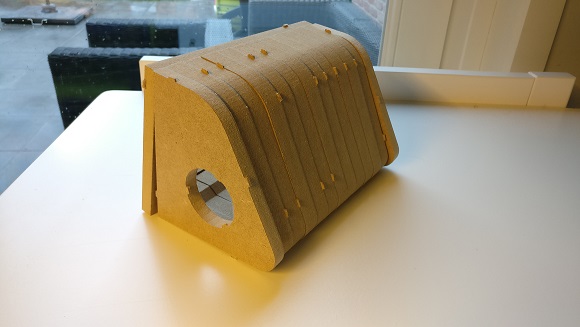
Rough cut - back
Applying the veneer
I ordered real Mahogany and Cherry wood veneer from HoutFineer. Typically you have to order these in sheets that are a couple of square meters large, but this site offered ‘scraps’ that were just the right dimensions for the project.
The front and sides are veneered in a semi dark Mahogany wood whilst the backside will have a light Cherry veneer contrasting it. The flat surfaces of the front and side panels were easily veneered using cement glue.
The veneer for the back was first soaked in hot water to make the wood fibres more flexible. It is important to soak them in hot water, as the fibres will remember their new (bent) shape once they cool and dry. This greatly reduces internal stresses within the wood and avoid tearing.
Then it was place within the forming mould without glue to receive its final shape. When the veneer had completely dried, we applied PVAC glue and let it dry in a well clamped down mould. We waited for twice the normal drying time as we applied a liberal amount of glue and not a lot of air could reach within the mould to hasten the chemical reaction.
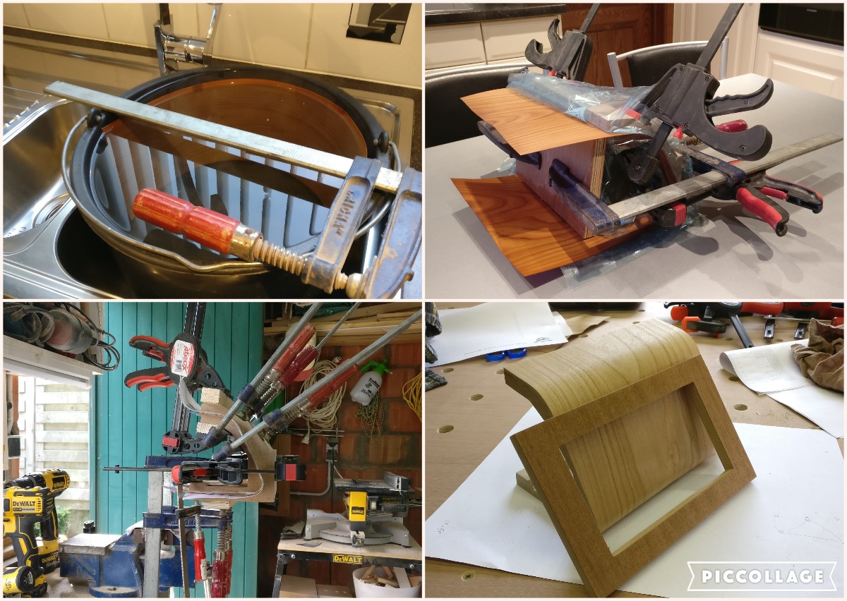
1. Soaking - 2. Glueless drying - 3. Clamped drying with glue - 4. Finished product
To be Continued
Next step will be to make sure all external electronics, such as power plug, power switch and speaker meshes are correctly placed. After this we can start joining the pieces to make the full enclosure.


