🎮 Game Boy Zero Build: Installing the Screen
For the screen I will be using a 3.5" BW backup screen for a parking camera system.
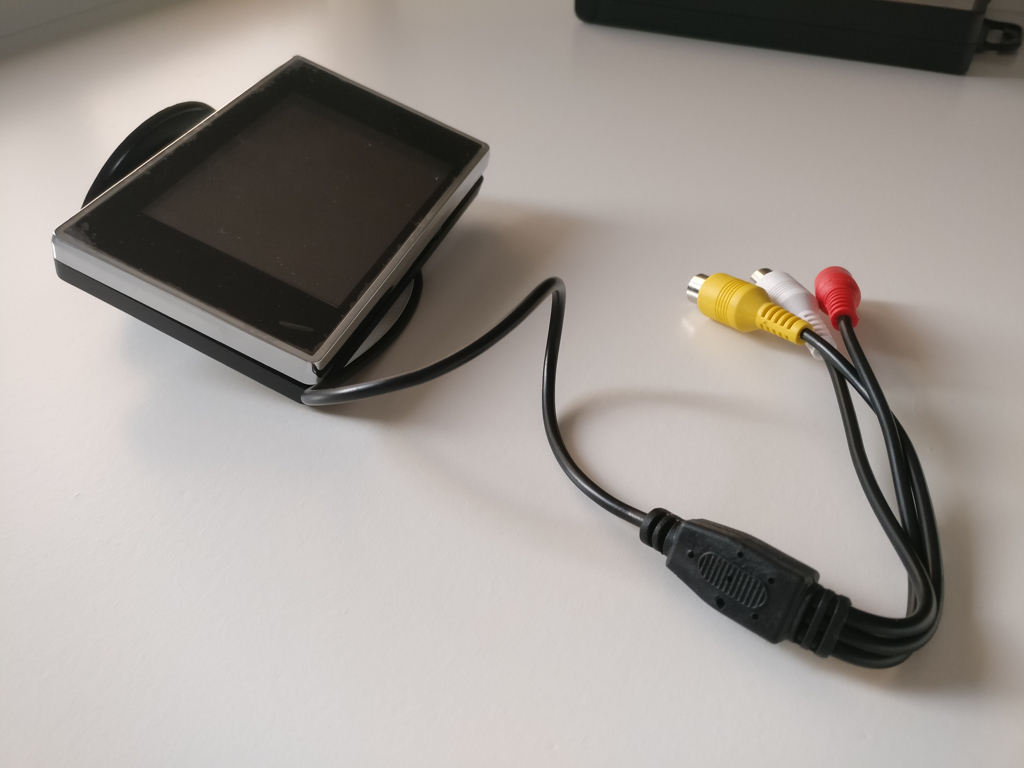
A cheap composite screen of the right dimensions
A benefit of this screen is the small footprint of its controller board. The additional button board houses the controls to adjust the screen’s brightness and contrast.
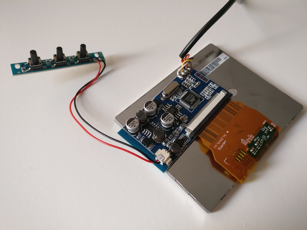
Small footprint display controller board, ideal when space is at a premium!
Specifications:
- Resolution: 320 x 240px
- Dimensions: 76 x 64mm
- Input type: Composite AV/CVBS
Power Issues
These boards are typically designed to be powered by an input voltage between 6V and 12V, which become a 5V and 3.3V rail respectively after passing through a series of regulators. Since I’m powering everything off of 5V rail already, I’ve added the red wire on the screen’s controller board to pass the 5V from the USB power directly to the 5V output of the first regulator.
After connecting the composite signal pads to the screen, I plugged in a USB charger in the Raspberry Pi Zero. The screen worked, but the image quality was terrible and contained a lot of flicker. The problem was easily fixed by hooking up a USB charger that supplied 5V at 1.5A; This was because because the raspberry and the screen consume more power than the initial USB charger could offer.
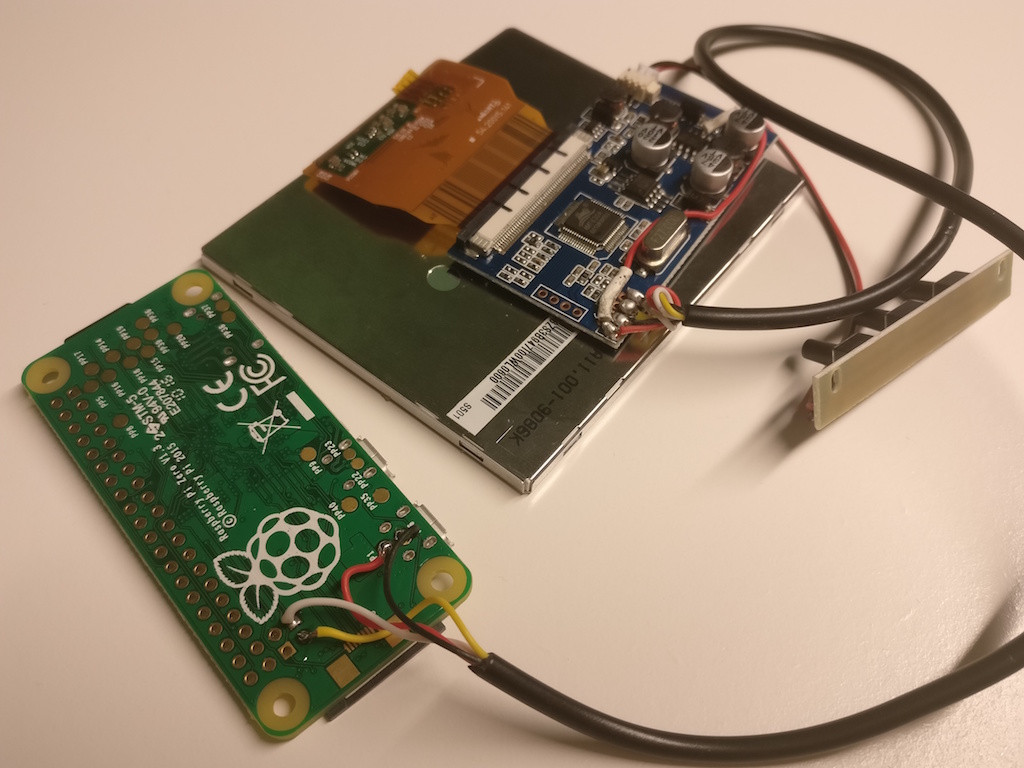
Test setup: Connecting the screen to a Raspberry Pi Zero
Installation
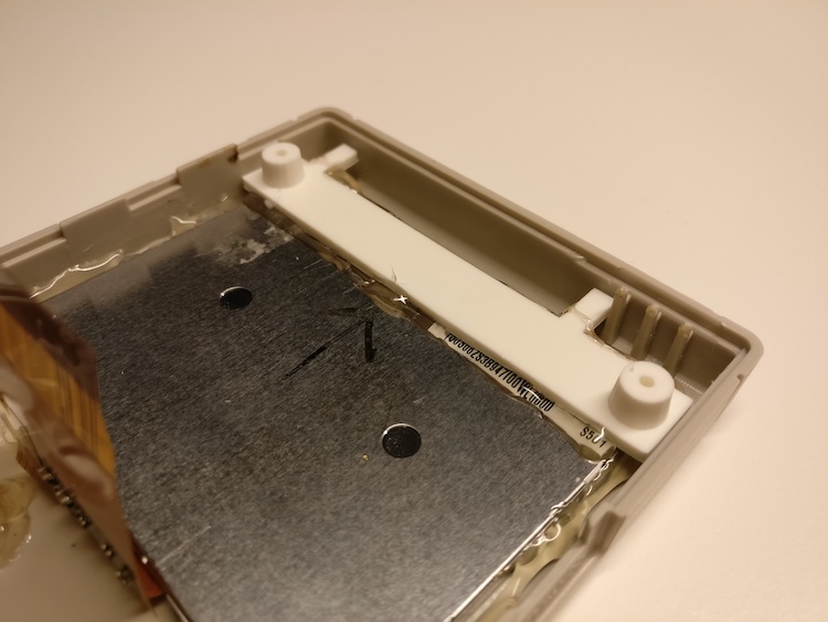
The screen is quite a bit bigger than a regular Game Boy screen. This meant increasing the screen cut-out of the casing. Cutting away as much as possible, I still left a small border of the inset around the screen to later glue on a screen protector.
However, creating space came at a cost: two of the screw holes need to be elimiated to allow for such a big screen. Since we are already going to use two screw holes for extra buttons (more on that later), we can’t afford to give up the top two screw holes. The case would only be screwed together on the bottom.
Luckily, some smart people on the internet had already figured out how to fix this and were happy to share a 3D model of a bracket containing two screw holes. We simply have to glue it in place above the installed screen and voila, two wild screw holes appear!